How Do You Know if a Turbo Is Double Ball Bearing
Organization Optimization: A Guide To Setting Up Your Turbocharger
The GarrettMotion.com website contains a lot of helpful data. It contains product information about turbos, intercoolers, and turbo kits. Information technology explains Garrett's model nomenclature, information technology goes over Garrett's technology and product development as well every bit our involvement with OEM's and Motorsports. It contains tech tutorials written past the engineers from Basic, to Avant-garde, upwards to the Expert level where detailed formulas are used to plot operating points on compressor maps to assist select the correct turbo.
It also contains News and what events we'll be at throughout the year besides as a distributor locator. The website has all-encompassing information, both general and technical. No matter what your experience level, you'll find data that will aid yous with your specific application or simply increase your cognition of turbos and turbos systems.
Application Information
The about of import things to understand earlier designing a arrangement is the application utilise and your horsepower target. Is it going to exist used for route racing, elevate racing or drifting or mayhap a street driven machine? The intended use greatly affects the turbo choice besides as the system components. A turbo organisation that works well for a ix second drag automobile is most likely non going to piece of work well for a drift car or road race auto. You also demand to accept a target flywheel horsepower in mind. The horsepower value will be used to help blueprint the entire arrangement. A turbo that is too large will spool very tiresome and a turbo that is too pocket-sized will not brand the ability you want.
Turbo Matching
Go to www.GarrettMotion.com or Heave Adviser.com
Every turbo has a range for horsepower and deportation. These values are on all of the performance turbo pages. The cardinal to identifying your potential turbo matches lies within these ranges. What is your target horsepower? What is your engine deportation? Side by side, detect the turbochargers that align with your requirements.
- Click on Turbo Tech • Read Turbo Techs 101, 102 and 103.
• Using formulas in Turbo Tech 103, calculate mass period and pressure level ratio (PR) at redline for your specific awarding.
• Plot mass flow and PR on several compressor maps to decide the best fit.
• For the case in this presentation, the "application" will be a 400 flywheel hp street car using pump gas, therefore the estimated mass flow ~ 40 lbs/min
Air Filter Selection
It is of import to appropriately size the air filter for the maximum catamenia rate of the application. A target confront velocity of ≤130 ft/min at redline is used to minimize brake and to provide the turbo with the air necessary for it to function optimally. If the turbo does not have admission to the proper amount of air, excessive restriction will occur and cause:
• Oil leakage from the compressor side piston ring, which results in oil loss, a fouled intercooler and potentially smoke out of the tailpipe.
• Increased pressure ratio, which tin can lead to turbo overspeed.
• Overspeed volition reduce turbo immovability and could result in early turbo failure.
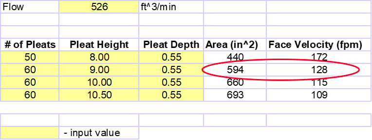
Determining the correct air filter size
Case:
Face up Velocity = 130 ft/min
Mass Flow = 40 lbs/min
Air density = 0.076 lbs/ft³
Mass Menstruum (lbs/min) = Volumetric Period Charge per unit (CFM) ten Air Density (lbs/ft³)
Volumetric Flow Rate (CFM) = Mass Menstruum (lbs/mn) / Air Density (lbs/ft³)
Volumetric Catamenia Rate = 526 CFM
For twin applications divide the flow rate past 2
Face Velocity (ft/min) = Volumetric Period Rate (CFM) / Area (ft²)
Area (ft²) = CFM / Face Velocity (ft/min)
Expanse (ft²) = 526 / 130 = 4.05
Surface area (in²) = iv.05 10 144
Area= 582 in²
How to decide filter size one time you know the calculated area
Area (in²) = pleat height x pleat depth x number of pleats 10 two
Area (in²) = ix.00 x .55 10 60 10 2
Area = 594 in²
Actual Filter Surface area (594 in²) > Calculated Area (582 in²)
Oil Supply & Drainage
Ball Begetting Turbo
An oil restrictor is recommended for optimal functioning with ball bearing turbochargers. Oil pressure of 40 – 45 psi at maximum engine speed is recommended to prevent damage to the turbocharger's internals. In guild to achieve this pressure, a restrictor with a 0.040" orifice volition normally suffice, but you should always verify the oil pressure level inbound the turbo after the restrictor to ensure the components function properly. Recommended oil feed is -3AN or -4AN line or hose/tubing with a similar ID. As always, employ an oil filter that meets or exceeds the OEM specifications.
OIL LEAKAGE SHOULD Not OCCUR ON A PROPERLY FUNCTIONING Arrangement IF RESTRICTOR IS NOT USED UNLESS THE SYSTEM PRESSURE IS EXCESSIVELY High.
Journal Bearing Turbo
Journal-bearings function similarly to rod or crank bearings in an engine – oil force per unit area is required to keep components separated. An oil restrictor is mostly not needed except for oil-pressure level-induced leakage. The recommended oil feed for periodical bearing turbochargers is -4AN or hose/tubing with an ID of approximately 0.25". Exist sure to utilise an oil filter that meets or exceeds the OEM specifications.
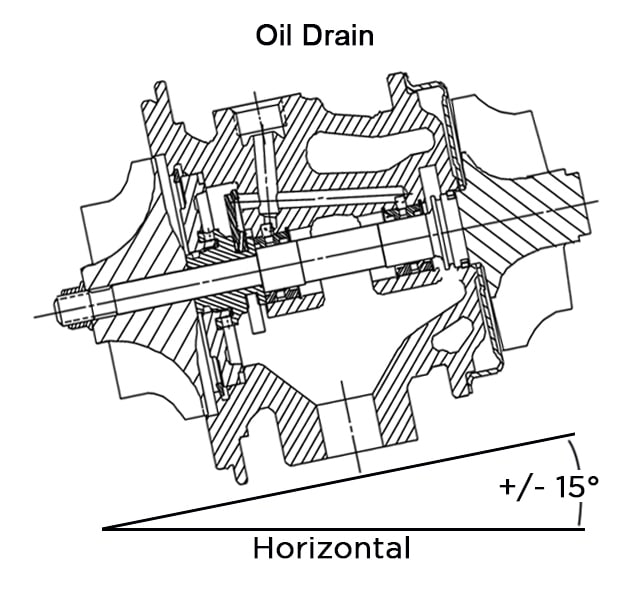
Oil Drain
In general, the larger the oil drain, the improve. However, a -10AN is typically sufficient for proper oil drainage, just try not to have an inner bore smaller than the drain hole in the housing as this volition likely crusade the oil to back up in the center housing. Speaking of oil backing upwards in the center housing, a gravity feed needs to be just that! The oil outlet should follow the direction of gravity +/- xv° when installed in the vehicle on level ground. If a gravity feed is not possible, a scavenge pump should be used to ensure that oil flows freely abroad from the center housing.
When installing your turbocharger, insure that the turbocharger axis of rotation is parallel to the level footing inside +/- 15°. This ways that the oil inlet/outlet should be within 15° of being perpendicular to level footing.
Avoid:
- Undulations in the line or extended lengths parallel to the ground
- Draining into oil pan beneath oil level
- Deadheading into a component behind the oil pan
- Surface area backside the oil pan (windage tray window) where oil sling occurs from crankshaft
Water Line Optimization
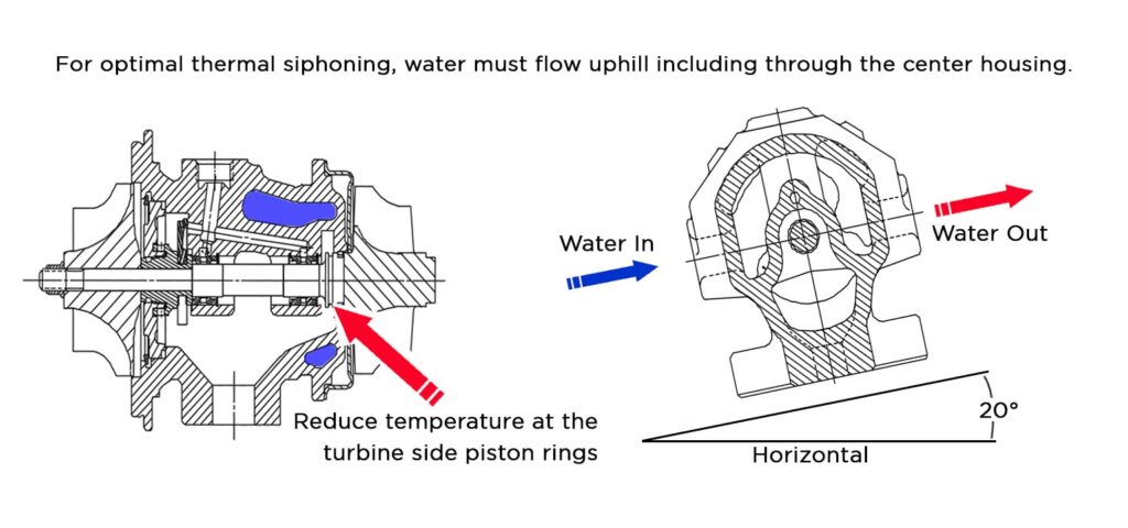
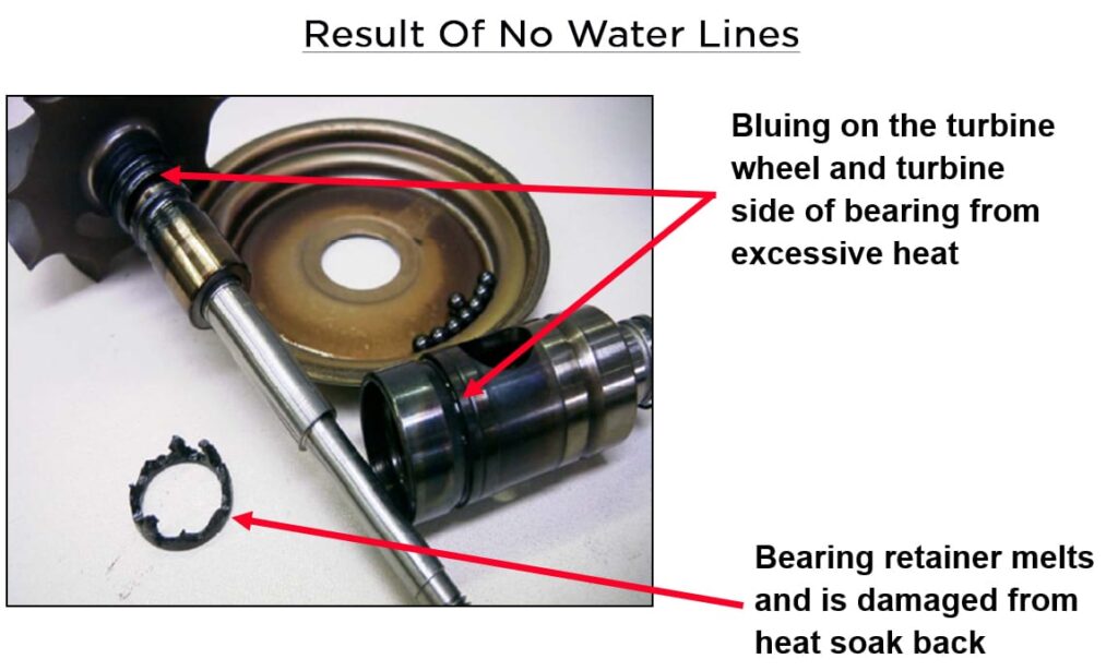
Water cooling is a central pattern feature for improved immovability and we recommend that if your turbo has an allowance for watercooling, claw up the water lines. Water cooling eliminates the destructive occurrence of oil coking by utilizing the Thermal Siphon Effect to reduce the Meridian Heat Soak Dorsum Temperature on the turbine side piston afterwards shut-downward. In order to get the greatest benefit from your water-cooling system, avoid undulations in the water lines to maximize the Thermal Siphon Consequence.
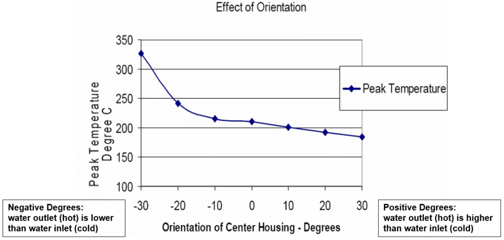
For best results, set the orientation of the heart housing to 20°. Significant impairment to the turbo tin can occur from improper water line setups.
Click here to read the full white paper on water cooling
Computing the Right Accuse Tubing
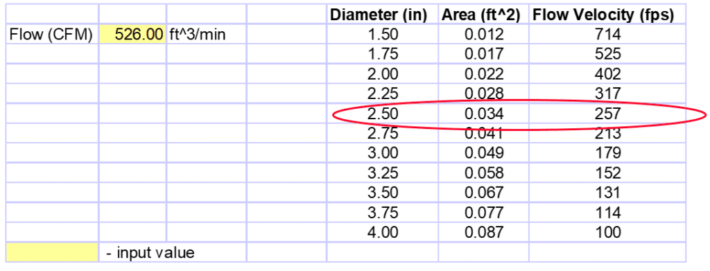
The duct diameter should be sized with the capability to menstruum approximately 200 – 300 ft/sec. Selecting a flow diameter less than the calculated value results in the catamenia force per unit area dropping due to the restricted flow area. If the diameter is instead increased above the calculated value, the cooling catamenia expands to fill the larger diameter, which slows the transient response. For bends in the tubing, a skillful design standard is to size the bend radius 1.5 times greater than the tubing bore. The flow surface area must be free of restrictive elements such as abrupt transitions in size or configuration.
For our example: Velocity (ft/min) = Volumetric Menstruum Rate (CFM) / Area (ft²)
• Tubing Diameter: velocity of 200 – 300 ft/sec is desirable.
Also modest a diameter volition increase pressure drib, too large can dull transient response.
• Velocity (ft/min) = Volumetric Flow rate (CFM) / Area (ft2)
Again, for twin turbo setups, split the flow rate by (2).
Charge tubing pattern affects the overall performance, so at that place are a few points to proceed in mind to become the best performance from your organisation.
- Duct curve radius:
– Radius/diameter > 1.5
• Period area:
– Avert surface area changes, precipitous transitions, shape changes
• Available packaging infinite in the vehicle usually dictates certain designs
Selecting a Charge Air Cooler
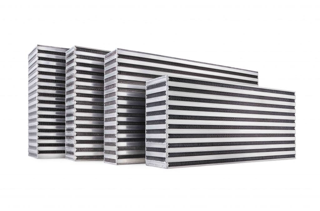
Selecting a accuse air cooler (aka intercooler) has been made simple with the Intercooler core page. Each core has a horsepower rating, making it easy every bit matching your desired power target to the core. In full general, use the largest core that will fit within the packaging constraints of the application.
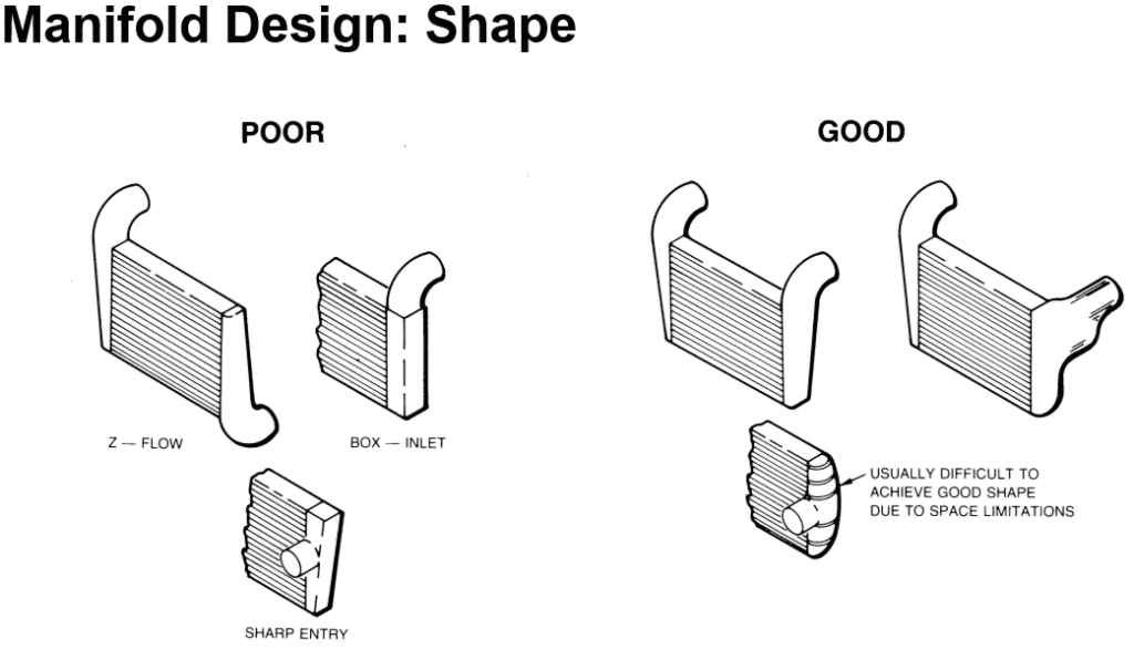
Another important factor in selecting the right intercooler is the stop tank pattern. Proper manifold shape is disquisitional in both minimizing charge air pressure drop and providing compatible flow distribution. Practiced manifold shapes minimize losses and provides even flow distribution. The over-the-acme design can starve the top tubes, however. The side entry is ideal for both pressure drib and flow distribution, just information technology is usually not possible due to vehicle space limitations.
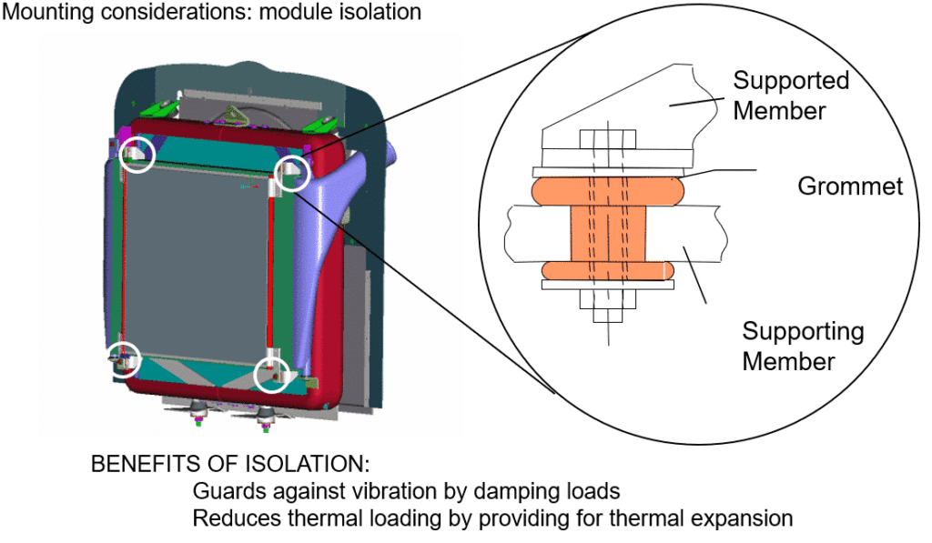
Proper mounting of the intercooler increases the durability of the system. Air to air accuse air coolers are typically "soft-mounted", meaning they apply rubber isolation grommets. This type of mounting is also used for the entire cooling module. The design guards against vibration failure by providing damping of vibration loads. It also reduces thermal loads past providing for thermal expansion.
Benefits of Isolation:
- Guards confronting vibration by damping loads
• Reduces thermal loading by providing for thermal expansion
Blow Off Valves (BOV)
Using the proper blow off valve (BOV) affects the system performance. There are 2 main types to consider.
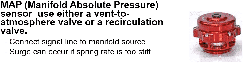
MAP (Manifold Absolute Pressure level) sensor uses either a vent to atmosphere valve or a recirculation valve.
– Connect signal line to manifold source
– Surge can occur if spring charge per unit is too stiff
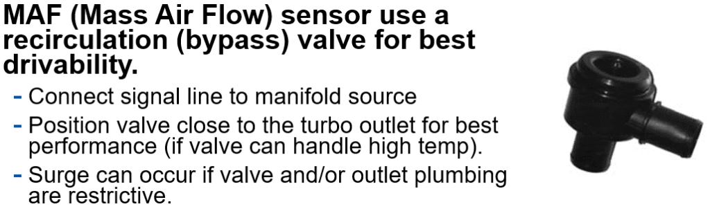
MAF (Mass Air Flow) sensor uses a recirculation (featherbed) valve for best drivability.
– Connect signal line to manifold source
– Position valve close to the turbo outlet for best performance (if valve tin handle loftier temp).
– Surge tin occur if valve and/or outlet plumbing are restrictive.
Wastegates
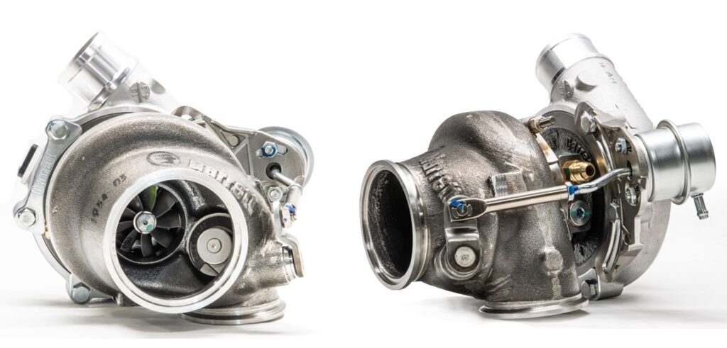
Internal wastegates are role of the turbo and integrated into the turbine housing. Two connectedness possibilities exist for signal line. The first is to connect line from compressor outlet (not manifold – vacuum) to the actuator. The 2d is to connect a line from compressor outlet to boost controller (PWM valve) and then to the actuator. Manifold force per unit area is limited by the spring rate of the actuator. Nigh OEM style actuators are non designed for vacuum, and thus, the diaphragm can be damaged resulting in excessive manifold pressure and engine damage.
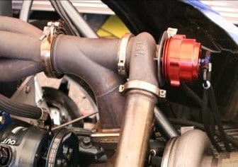
External wastegates are separate from the turbo and integrated into the exhaust manifold rather than the turbine housing. Connection to the manifold greatly affects menses capability, and correct orientation of the wastegate to the manifold is essential. For example, placing the wastegate at ninety° to the manifold will reduce period capacity past upwards to fifty%! This profoundly reduces the command that yous have over the system and puts your entire drivetrain at hazard. Instead, the ideal connection is at 45° with a polish transition.
There are two connection possibilities for signal line to an external wastegate:
• Connect a line from the compressor outlet (not manifold – vacuum) to the actuator
• Connect a line from the compressor outlet to a boost controller (PWM valve) and and then to the actuator. Again, manifold force per unit area is limited by spring charge per unit of actuator.
Oil Leakage
A properly installed turbo should Non leak oil. There are, however, instances where oil leaks occur. Here are the most common causes, depending on the location of the leak.
Leakage from compressor and turbine seals
– Excessively loftier oil pressure
– Inadequate drain – drain is too small, does not go continuously downhill, or the location of the bleed within the oil pan is located in a section that has oil slung from the creepo causing oil to dorsum up in drain tube. Always place oil bleed into oil pan in a location that oil from crank is blocked by windage tray.
– Improper venting of crankcase force per unit area.
– Excessive crankcase pressure.
– Oil drain rotated past the recommended 35°.
Leakage from compressor seal
Excessive pressure beyond the compressor housing inlet acquired by:
– Air filter is too small.
– Accuse air tubing too small or has as well many bends between the air filter and compressor housing.
– Chock-full air filter.
Leakage from Turbine seal
– Collapsed turbine piston band from excessive EGT'due south.
– Turbo tilted back on its axis past recommended xv°
Testing Your Turbo System
Many problems with turbo systems tin be identified before the catastrophic happens through unproblematic system testing.
Pressurize organisation to test for leaks
- Clamps – Check tightness
- Couplers – Check for holes or tears
- CAC core / terminate tanks – Check for voids in welds
Monitoring
The turbo system in your car should be monitored to insure that every attribute is performance properly to give you problem-complimentary performance.
Instrumentation used to monitor / optimize organisation: The well-nigh accurate way to calibrate and optimize a arrangement is through data logging!
- Oil Pressure (Required to monitor engine operation)
ii. Oil Temperature (Required to monitor engine operation)
iii. Water Temperature (Required to monitor engine operation)
4. A/F Ratio (such as a wideband sensor; required to monitor engine operation)
five. Manifold Force per unit area
6. Turbine Inlet Pressure
7. Exhaust Gas Temperature
8. Turbo Speed Sensor
Manifold Pressure level
– Calibrate actuator setting to accomplish manifold pressure required to encounter hp target
– Detect over-boost condition
– Notice damaged actuator diaphragm
Dorsum Force per unit area
– Monitor pressure level changes in turbine housing inlet
– Affect of different turbine housing A/R's
– Increased back pressure decreases Volumetric Efficiency thus decreasing ultimate ability
Pyrometer
– Monitor frazzle gas temperature (EGT) in manifold / turbine housing
– Adjust calibration based on temperature rating of turbine housing material or other exhaust components Turbo Speed
– Make up one's mind operating points on compressor map
– Determine if the electric current turbo is correct for the application and target hp
– Avoid turbo over-speed condition, which could damage turbo
xi Point Checklist
- Application Information – target horsepower, intended utilise of vehicle, etc.
2. Air filter sizing – determine size for application needs
3. Oil Supply – restrictor for ball-bearing turbo
iv. Oil Drain – proper size and routing
5. Water Lines – set for greatest thermal siphon effect
6. Charge Tubing – make up one's mind bore for application needs
7. Charge-Air-Cooler – determine core size for awarding needs, design manifolds for optimal menstruation, mount for durability
8. BOV – VTA for MAP engines and by-laissez passer for MAF engines
ix. Wastegate – connect indicate line to compressor outlet, smooth transition to external wastegate
x. System Testing – pressurize system to check for leakage, periodically cheque clamp tightness and the condition of
couplers
xi. System Monitoring – proper gauges/sensors to monitor engine for optimal performance and component durability
How Do You Know if a Turbo Is Double Ball Bearing
Source: https://www.garrettmotion.com/racing-and-performance/choosing-a-turbocharger/turbo-system-optimization/
Post a Comment for "How Do You Know if a Turbo Is Double Ball Bearing"